 English
 Español
 Inquiry
A rotary file cutting aluminum faces a very different task from one working on stainless steel or titanium. Aluminum tends to produce soft, sticky chips that can clog the teeth. Stainless steel can harden under repeated contact, while titanium holds much of the cutting heat close to the workpiece. Nickel-based alloys are harder to machine because they retain their strength at high temperatures.
These differences put considerable pressure on the cutting edges. For a Rotary Files Factory, tooth geometry cannot be treated as a standard feature shared by every product. The spacing, angle, depth, and shape of the teeth all need to suit the material being removed.
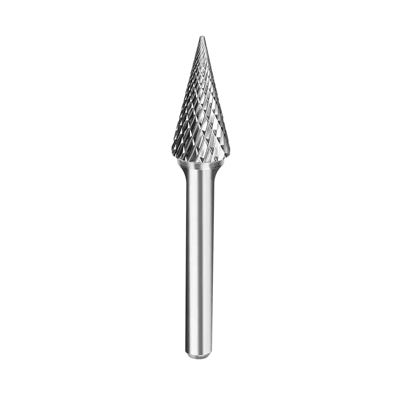
Why Difficult-to-Machine Metals Need Different Tooth Designs
A rotary file does not cut efficiently when its teeth simply rub against the workpiece. In stainless steel, repeated rubbing can cause work hardening, making the next cutting pass more difficult. With titanium, poor heat dissipation can accelerate wear around the cutting edge. Nickel-based alloys create another problem: high cutting resistance remains even as temperatures rise.
The tooth profile has to manage several conditions at once. Chips need room to leave the cutting area, the edge must stay sharp enough to cut rather than rub, and the tooth itself needs enough support to withstand cutting loads. If one of these factors is overlooked, the file may clog, vibrate, wear quickly, or leave an inconsistent surface.
A pattern that performs well on aluminum is not automatically suitable for stainless steel. The difference lies in chip behavior and cutting conditions as much as material hardness.
Three Tooth Geometry Factors That Affect Cutting
1. Rake Angle and Edge Strength
Rake angle influences how a tooth enters the metal and separates a chip. A more positive rake generally reduces cutting resistance, allowing the edge to cut more freely. The drawback is that less material supports the cutting edge, which can make it vulnerable to chipping under heavy loads.
A smaller or less aggressive rake leaves a stronger edge. This can be useful when machining tough alloys, although the tool may require more force to remove the same amount of material.
Neither approach works for every application. A profile intended for fast stock removal may sacrifice some edge durability, while a stronger profile may be better suited to sustained work on demanding alloys.
2. Tooth Pitch and Chip Clearance
Tooth pitch determines the distance between adjacent teeth and affects the space available for chip formation. Wider spacing usually creates larger chip pockets, which can help when removing substantial amounts of material.
Finer tooth patterns provide more cutting edges over a given area and can produce a more controlled finish. However, closely spaced teeth leave less room for debris. If the chips cannot escape, they may collect between the teeth and increase friction.
This is particularly relevant when cutting ductile materials. Aluminum, for example, often needs a more open tooth arrangement to reduce chip buildup. A fine pattern that works well for finishing another metal may become clogged during aluminum machining.
3. Single-Cut, Double-Cut, and Aluminum-Cut Patterns
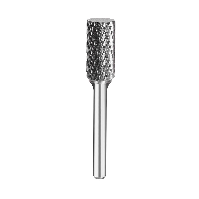
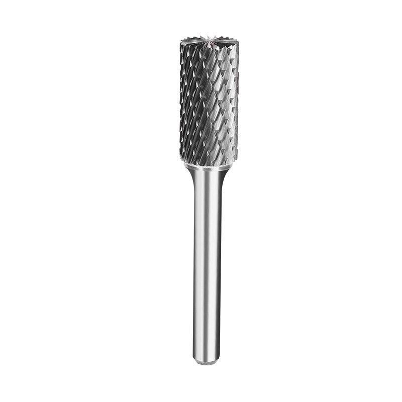
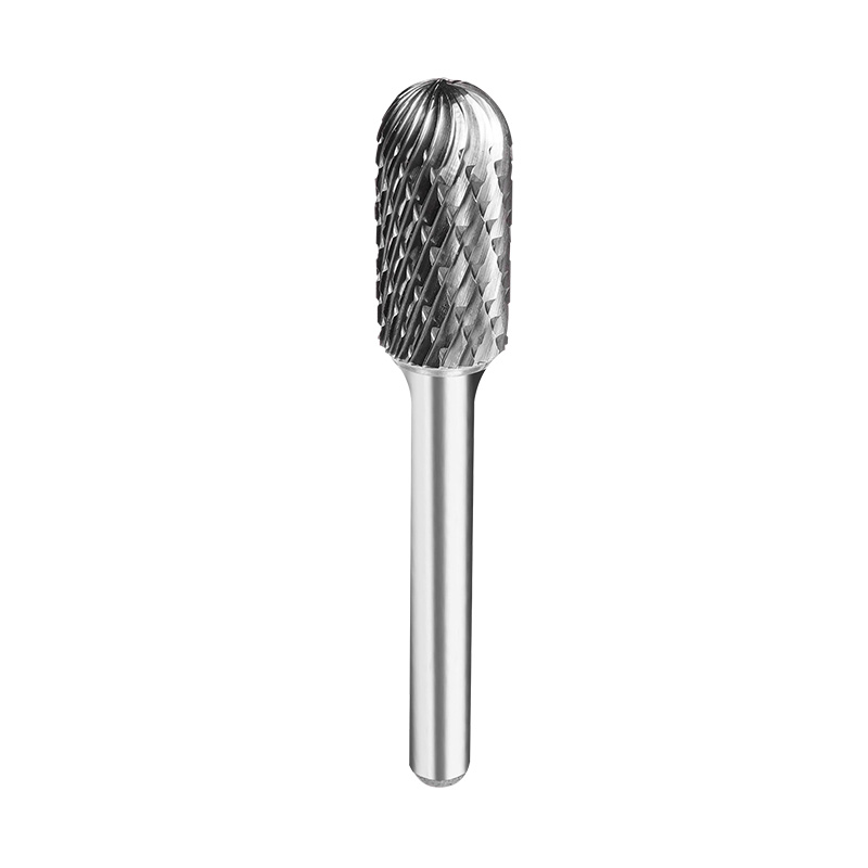
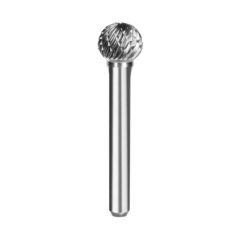
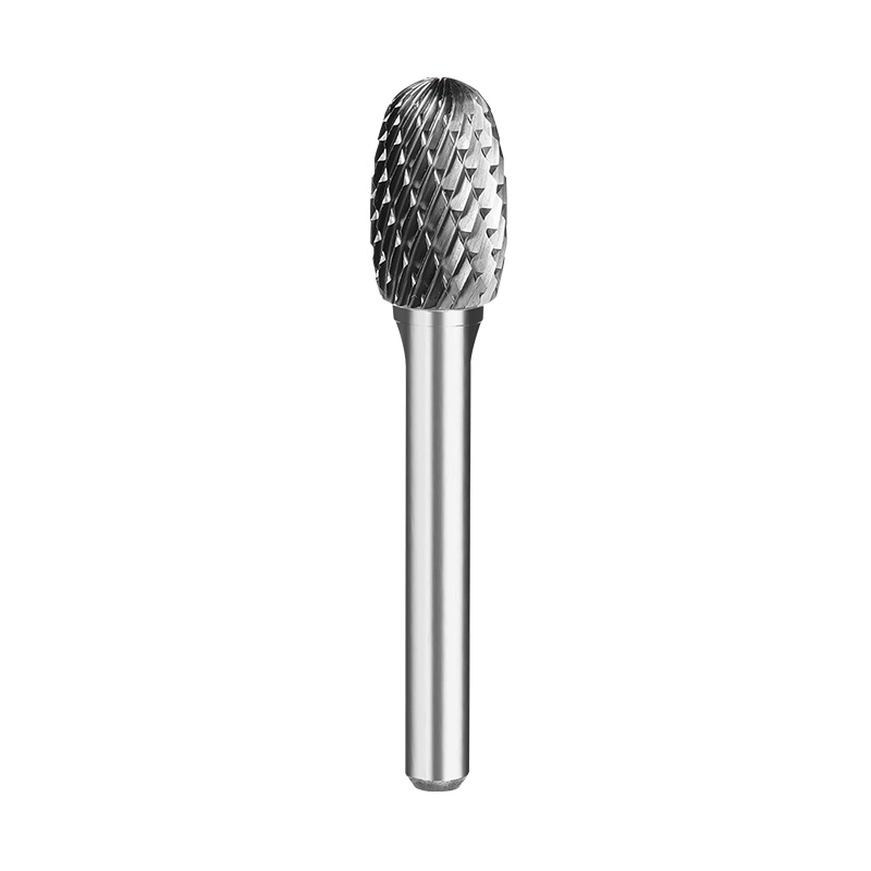
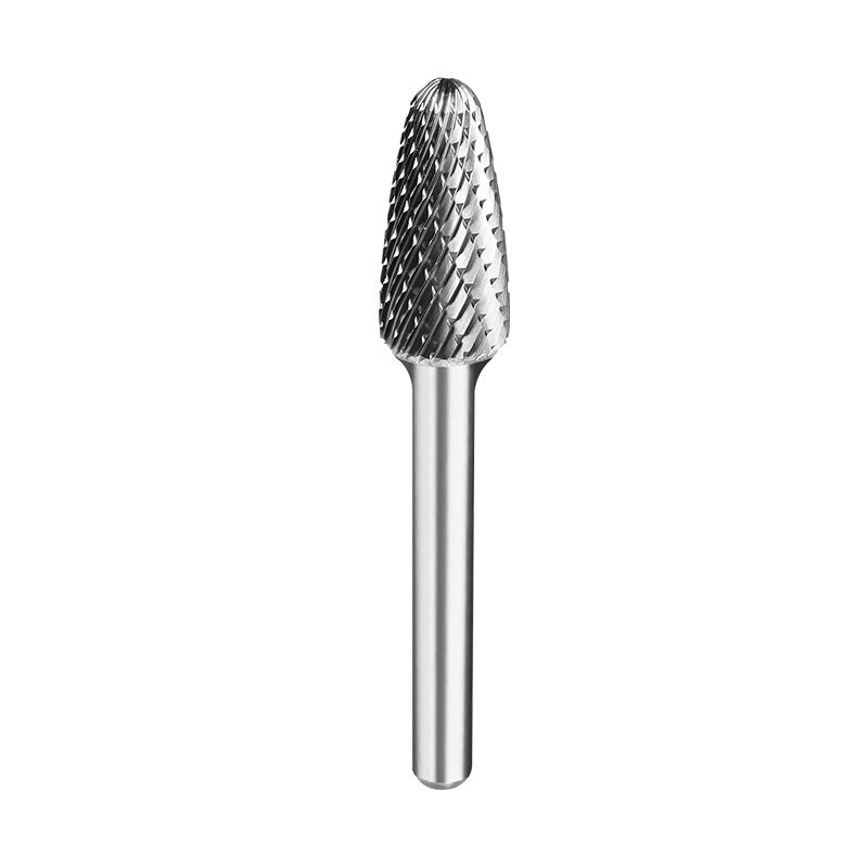
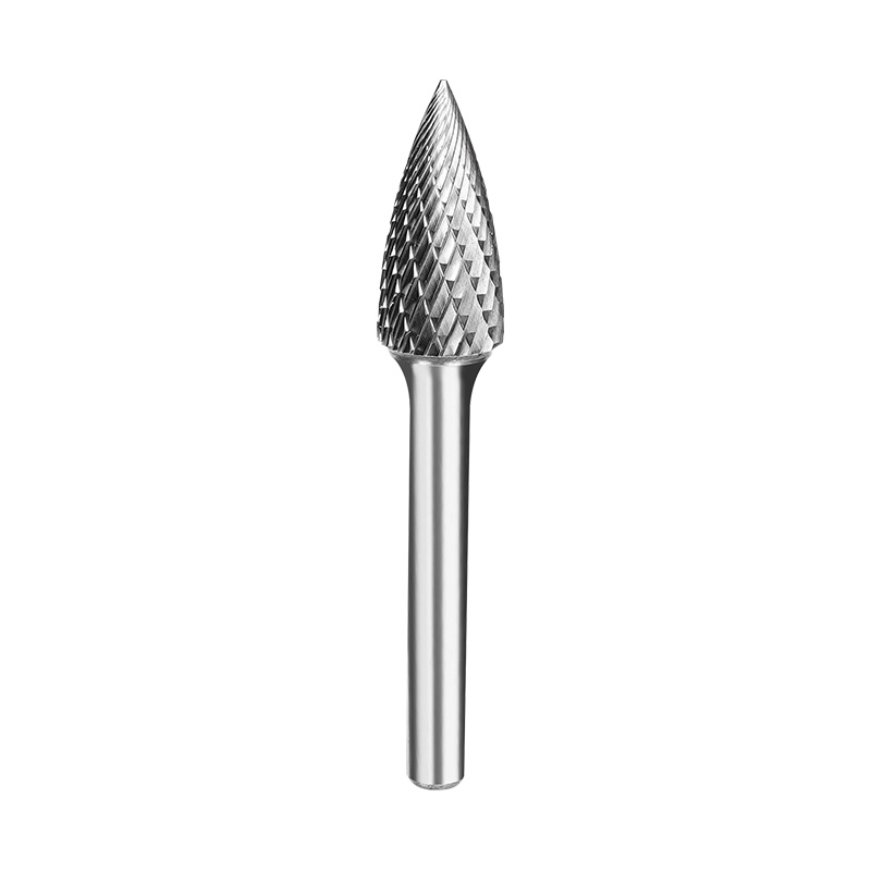
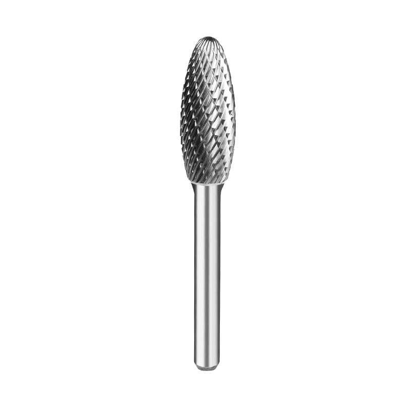
Single-cut files have one primary set of cutting teeth. They are often used for controlled material removal and applications where a relatively smooth cutting action is preferred.
Double-cut files have two intersecting tooth patterns. They break the material into smaller chips and are commonly used for general deburring and finishing. Aluminum-cut patterns use more open teeth to give soft, sticky chips additional clearance.
The pattern name alone does not tell the whole story. Tooth angle, spacing, and depth still affect how the file performs on a particular workpiece.
Tooth Design Considerations by Workpiece Material
| Material | Common Machining Difficulty | Tooth Geometry Consideration |
|---|---|---|
| Stainless Steel | Work hardening and heat generation | Sharp cutting edges and effective chip clearance |
| Titanium Alloys | Concentrated heat and high cutting resistance | Supported edges and controlled chip formation |
| Nickel-Based Alloys | High cutting loads and elevated-temperature strength | Wear-resistant edges and stable geometry |
| Hardened Steel | High hardness and edge loading | Strong, durable teeth |
| Aluminum Alloys | Chip adhesion and flute clogging | Open spacing and larger chip pockets |
These are development guidelines rather than universal specifications. Different grades and heat treatments can change how a metal responds during cutting. A profile intended for one stainless steel grade, for example, may not deliver the same results on another.
How a Rotary Files Factory Maintains Tooth Accuracy
A tooth design only works as intended if production can reproduce it consistently. Small differences in flute depth, tooth spacing, or cutting angle can change the way a rotary file engages with the workpiece.
Carbide selection is one of the first decisions. Tungsten carbide is widely used because it combines high hardness with good wear resistance, but carbide grades do not all behave alike. Greater hardness does not automatically mean better performance. Applications involving impact or interrupted cutting may need more toughness to reduce the risk of edge failure.
Grinding determines the finished tooth geometry. CNC grinding helps control flute dimensions and cutting angles across production batches. Concentricity also needs attention: if the cutting head runs unevenly against the shank, the file may vibrate or place too much load on only part of the cutting surface.
Edge condition matters just as much as overall dimensions. Grinding defects and small irregularities can become points where chipping begins. For rotary files with brazed carbide heads, the joint between the head and shank also requires inspection.
How Performance Testing Exposes Design Problems
Dimensional inspection can confirm that a tooth profile matches its drawing, but it cannot show exactly how the file will behave during cutting. That requires testing on the intended workpiece.
Useful measurements include material removal rate, surface roughness, edge wear, chip evacuation, and cutting stability. Testing should use consistent workpiece material and hardness, along with controlled rotational speed, feed pressure, and engagement depth. Otherwise, differences in operating conditions can distort the comparison.
Speed and pressure deserve particular attention. Excessive rotational speed can generate additional heat and vibration. Too much pressure may also prevent the teeth from cutting cleanly, causing rubbing and faster wear. Recommended operating speeds should take file diameter, workpiece material, and equipment limits into account.
What B2B Buyers Should Check Before Ordering
A catalog description rarely provides enough information to judge whether a rotary file will suit a demanding application. Buyers should ask about carbide grade, tooth configuration, cutting head dimensions, shank tolerances, and the materials for which the profile has been tested.
For titanium or nickel-based alloys, sample testing is especially useful. Check not only how quickly the file removes material, but also whether chips clear properly, whether the surface finish remains acceptable, and how much edge wear appears after repeated use.
Consistency across samples matters too. One well-made sample does not guarantee that a large production batch will behave the same way. Dimensional inspection records, production controls, and batch traceability provide a clearer picture of the factory's manufacturing capability.
Improving Rotary File Performance Through Tooth Geometry
Stainless steel, titanium, nickel-based alloys, and aluminum place different demands on a rotary file. Their tooth profiles need to reflect those differences, particularly in edge support, cutting angle, and chip clearance.
For a Rotary Files Factory, the work involves more than producing several tooth patterns. Each design must be ground accurately, checked during production, and tested against the material it is intended to cut. Buyers sourcing industrial rotary files should pay close attention to those details rather than relying on a tooth-pattern name or catalog description.
Cooperate with us now
contact Us
Characteristic Industrial Park, Furong Town, Yueqing City, Zhejiang Province, China.
+86-13757799073
+86-13587713956

Wholesale Carbide Rotary Burs Factory